From Scratch
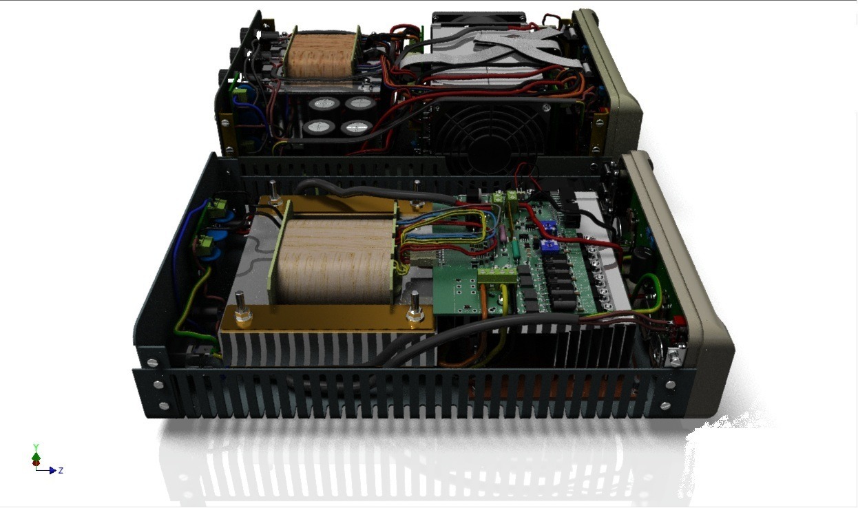
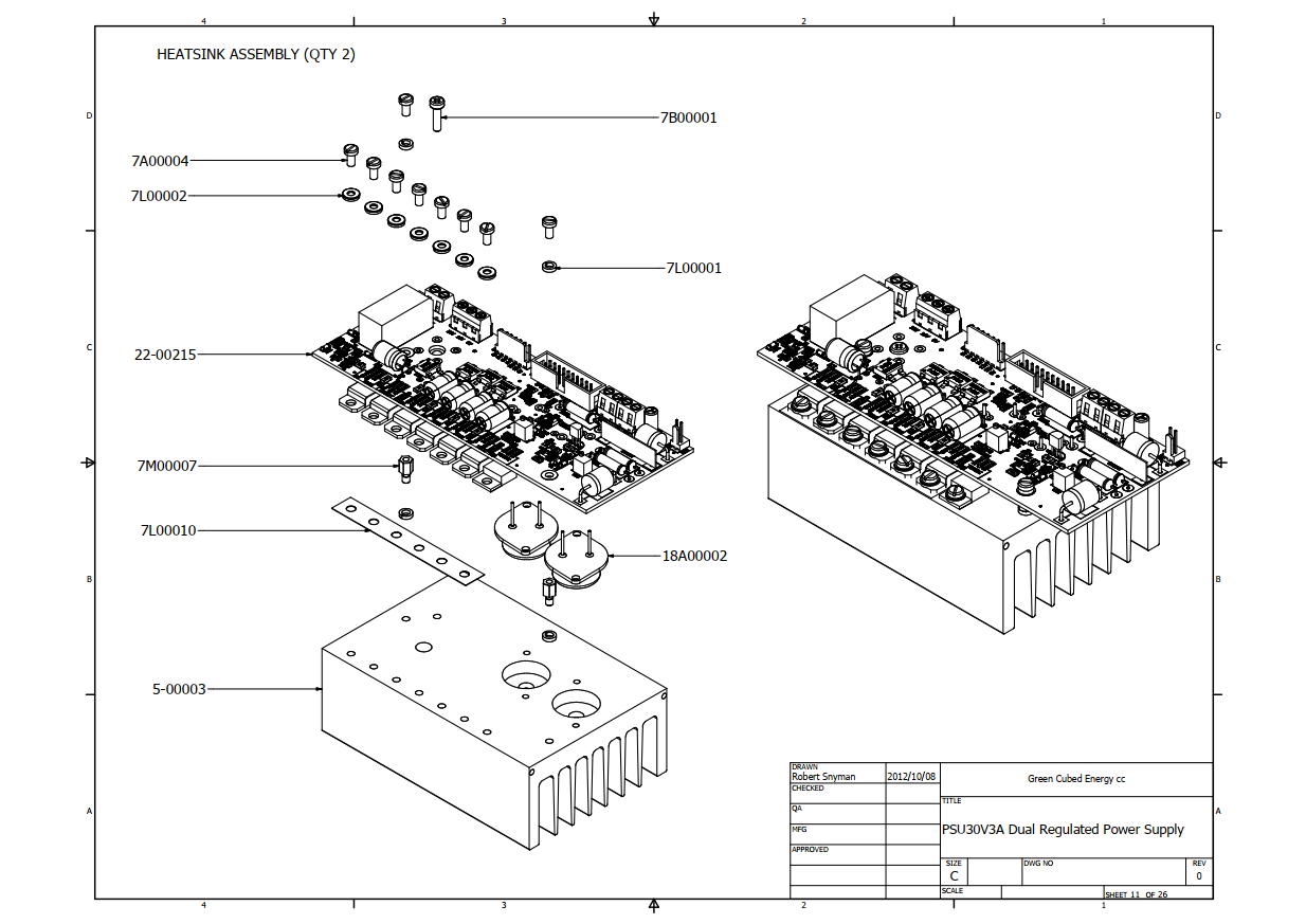
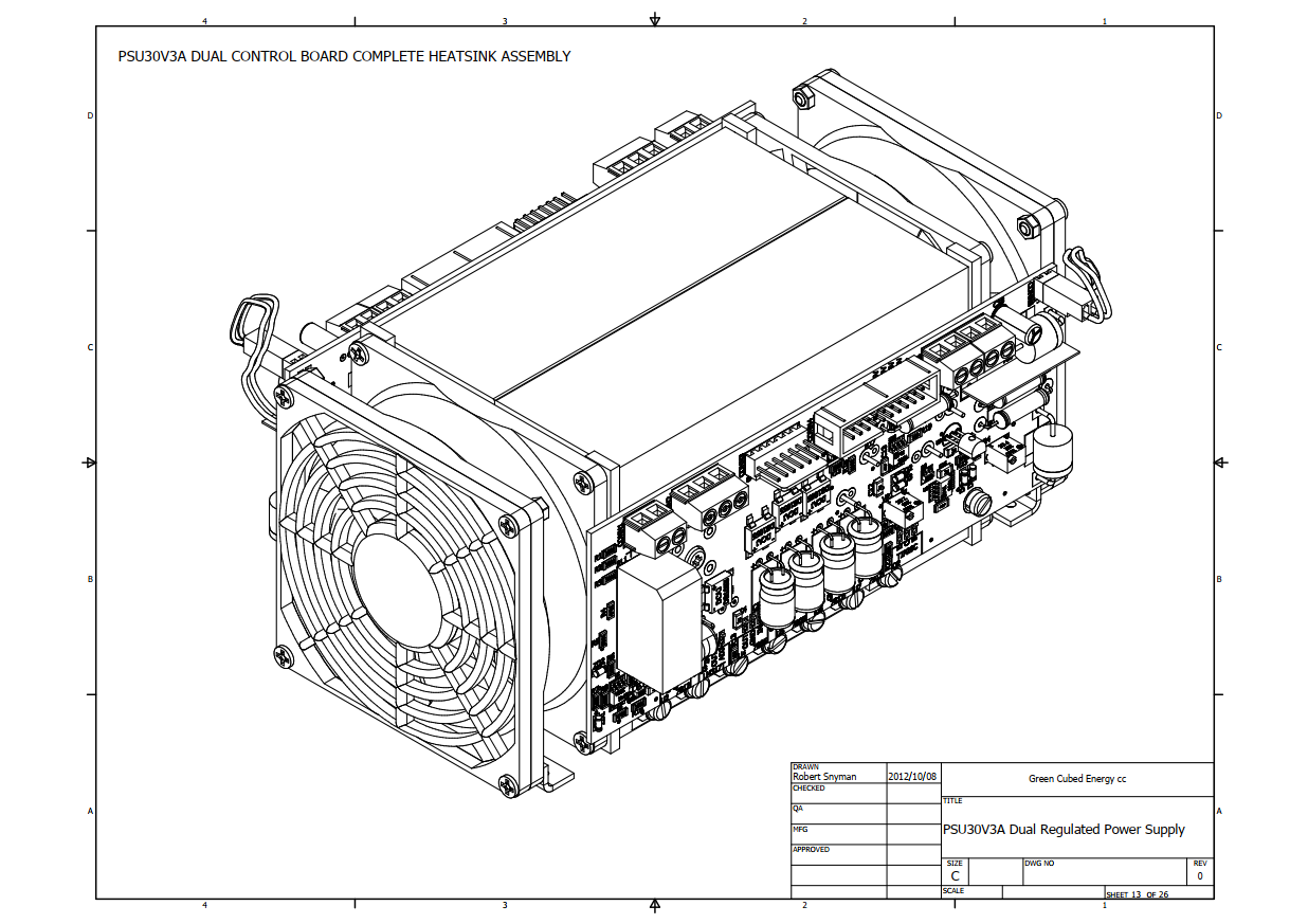
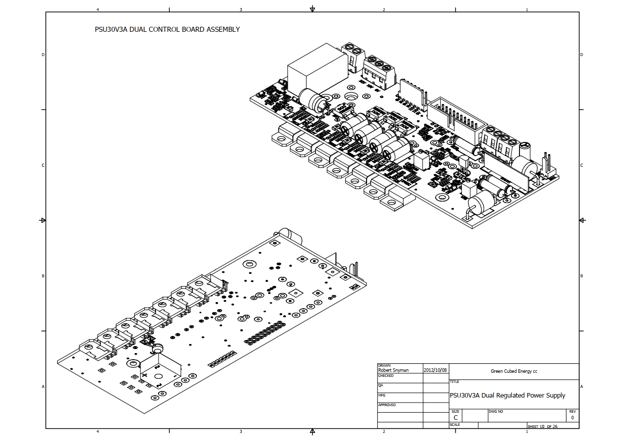
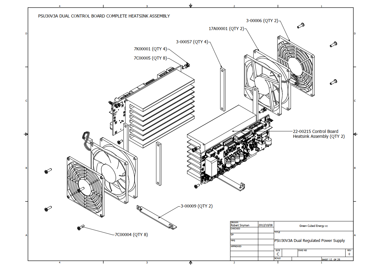
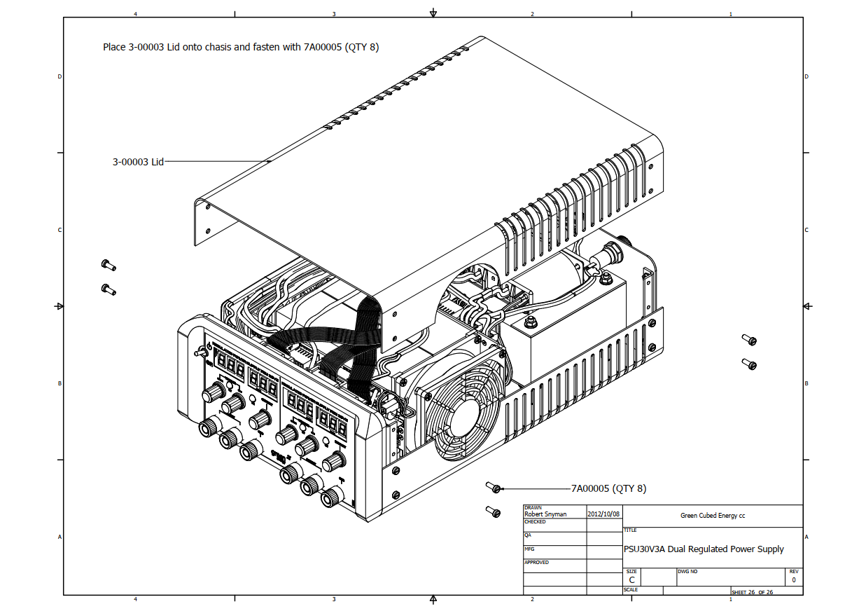
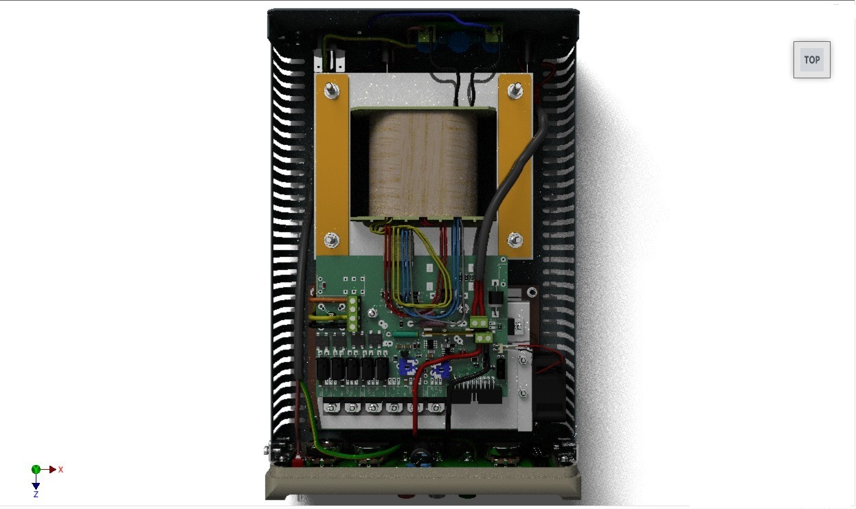
The reactions of disbelief from my colleagues never gets old when I tell them that all the components in these assembly models were done from scratch. Back in 2012 when I started my career in the private sector when I was hired as the mechanical designer at Clearline Protections Systems, the company that specializes in lightning & surge protection, my main role was to produce detailed product assembly manuals. Though I did work in research & development and was involved in designing new products, prototyping, and testing, creating these assembly manuals of the existing products, as well as the new ones took priority since assembling them was outsourced to contractors since Clearline didn't have a production department. Not only that, but there were always updates made to the hardware, so I had to keep the manuals updated as well.
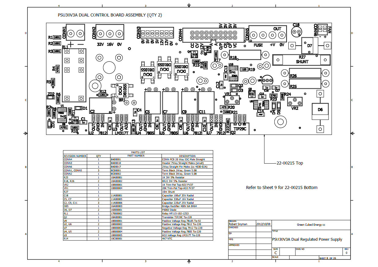
What made it challenging was that the electronic design engineers in R&D used a program called Easy PC to design their printed circuit boards (PCBs), which unfortunately didn't have 3D model capabilities, or to export the PCBs complete with electronic components that could be imported into my design software, or at least not at the time. So, I would have Easy PC open on one screen and Inventor on the other, and I would measure every detail from their PCB design layout, and I do mean every detail while modeling the PCBs in 3D on Inventor. Now unlike the normal method of designing PCBs where you would have footprints for components at your disposal, modeling a board from scratch was painstaking. This entailed all the silk detail, the pads, and in some cases the tracks as well. And especially the through-holes... God, there were a lot of through-holes! Depending on the level of detail of each board, it could take well over a week to complete just the single part model. Aside from that, It took months to compile my own library of 3D models, such as electronic through-hole and surface mount components, which include resistors, capacitors, inductors, diodes, transistors, relays, regulators, LEDs, IC's, connectors, etc., all of which I modeled from scratch by pulling dimensions from the actual components with a vernier (a modeler's most trusted tool) in order to make the full assembly models of each PCB.
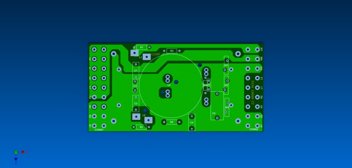
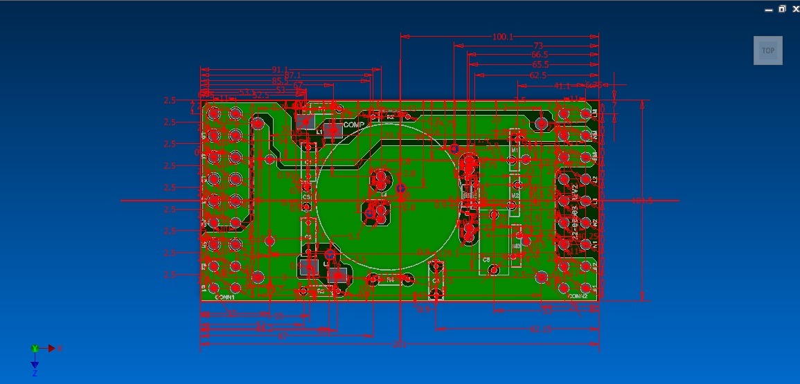
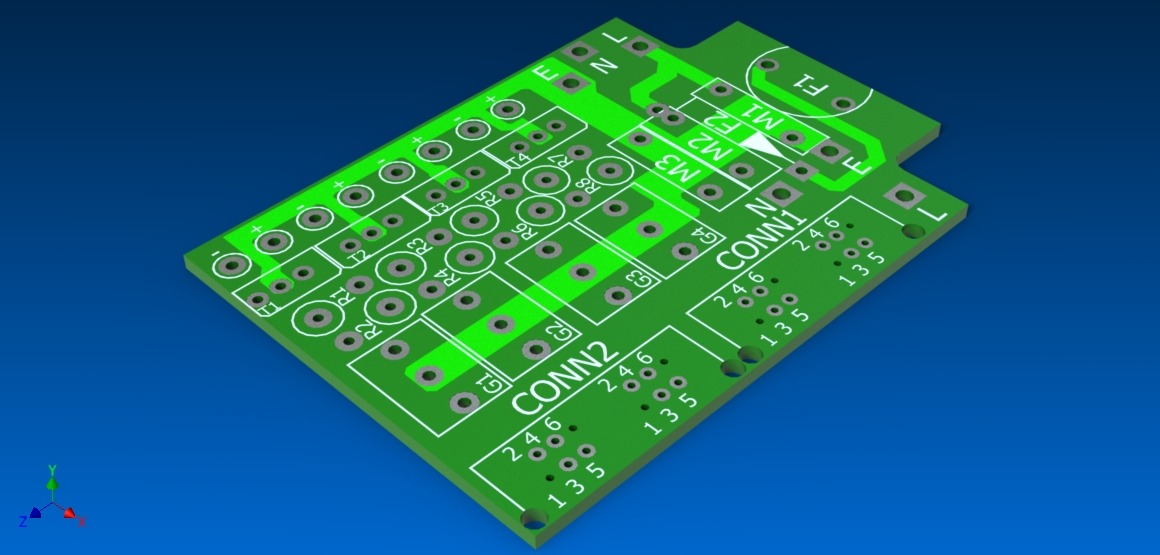
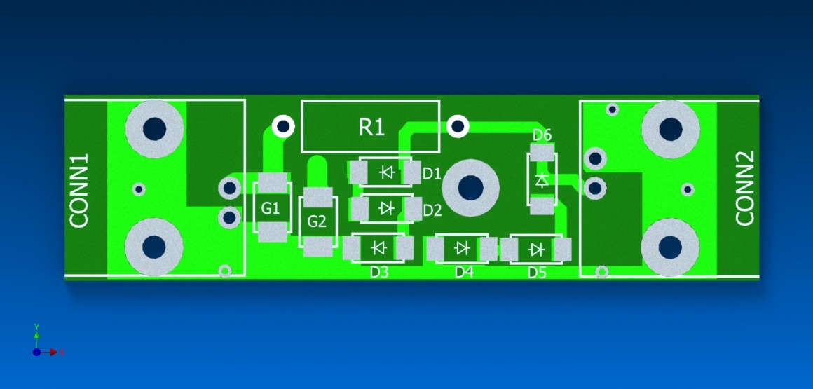
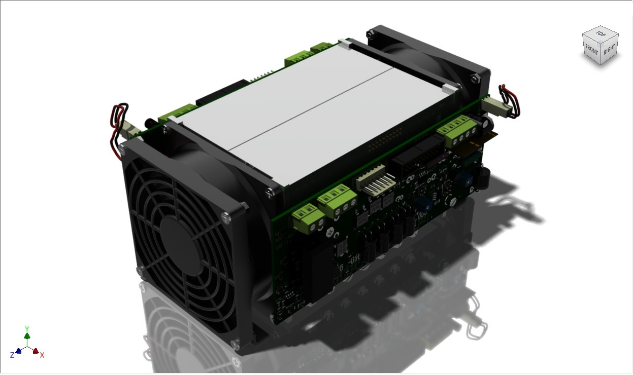
Usually with a good PCB designing software, fancy documents with drawings of the PCB can be generated to show where each electronic component should be soldered. I suppose Easy PC didn't have that capability either, and this is why I had to model them to precision. To add the PCB to the rest of the product's assembly manual.
But in the end it all paid off and I am quite proud of the work I did. Thinking back to my time there and all the projects I worked on, those are good memories.
